Automatic Attenuator
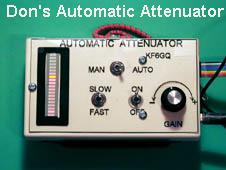
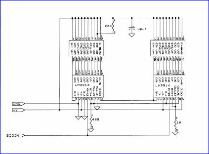
The reason behind designing an automatic attenuator is that too many times I've passed by a lower powered transmitter, because I forgot to turn off the attenuation being used on the stronger signal. This attenuator uses the front end of the radio used to control the gain of the first stages. The radio that I use is the Kenwood TR-751A. This could also be used on other type radios, but would require some changes to the control voltages used. At a minimum 3 wires need to come from the radio. Ground, S-meter signal, and the gain control voltage going back to the radio. I use more; available in the radio are several voltages that can be used with this setup. +13.6 switched, +8V, -8V. In the attenuator that I'm going to explain, I only use the +8V and I generate the -8V internally. I use twenty Led display, but any amount of Led’s can be used. Just adjust the circuitry appropriately. The Led display actually does several things, it of course shows the relative strength of the signal, but it also shows the relative setting of the attenuator. The Led display uses the LM3914 Led driver.
Now the description of the circuitry:
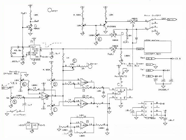
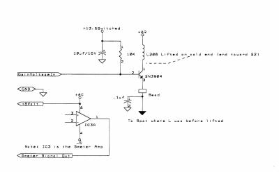
The S-meter comes into pot 3; this is used to trim the full-scale voltage of the s-meter so that it corresponds to full scale on the led meter. This goes to a buffer amp, so as to not load down the s-meter circuit in the 751. The buffer has another input, that is use to set the zero signal level at the first led. The output of this amp goes through a 1K resistor to an analog gate 4066 pin 4. Also it goes to the .5uf (.47uf) cap that is held to ground until TLC555 pin 7 lets it go (note: must use the CMOS versions of the 555 NOT the LM555). The output is /clk and also goes to a 4066 inverter to produce a clk signal. The attenuation control voltage is varied by the 10K 10-turn pot (not numbered). This signal goes through an emitter follower 2N3906; this signal goes to an analog gate 4066 pin 11. This gate turns off the attenuation voltage going to the 751, when it is not needed. The TL084 is a quad op-amp chip, one of the amps (pins 12,13,14) is used as a clock for the 4027-control toggle, and this clock runs at about 1HZ. The two other are used as level detectors. The lower one serves, as the point where the attenuator will turn off, and the upper one determines at what level the attenuator will kick in. In between the attenuation will stay as set. I set mine at about 15-20% and above 90%. The 4027 toggle will toggle to the state that these two level detectors dictate. Down in the lower right corner is a capacitive level converter that produces the negative voltages necessary for the proper operation of the op-amps. (Note: you might choose to use a rail-to-rail op-amp and maybe not need the negative voltage converter 7662). The buffer amp also can drive an analog meter through the pot 5 and 3K, if you want. Also on the input a fast/slow switch slows the signal down a bit when heavy modulation may cause bouncing of the s-meter.
Okay, this is for the 751A Auto Attenuation Mods.